Home /
Expert Answers /
Civil Engineering /
the-composite-shaft-shown-in-the-figure-consists-of-a-solid-brass-segment-1-and-a-solid-aluminum-pa129
(Solved): The composite shaft shown in the figure consists of a solid brass segment (1) and a solid aluminum ...
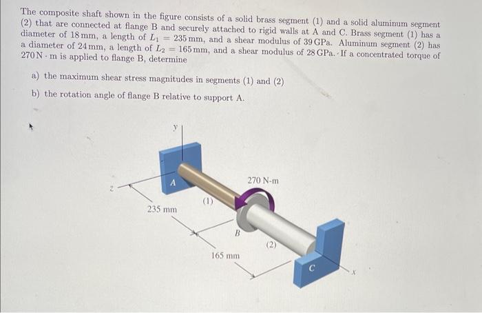
The composite shaft shown in the figure consists of a solid brass segment (1) and a solid aluminum segment (2) that are connected at flange \( \mathrm{B} \) and securely attached to rigid walls at \( \mathrm{A} \) and \( \mathrm{C} \). Brass segment (1) has a diameter of \( 18 \mathrm{~mm} \), a length of \( L_{1}=235 \mathrm{~mm} \), and a shear modulus of \( 39 \mathrm{GPa} \). Aluminum segment (2) has a diameter of \( 24 \mathrm{~mm} \), a length of \( L_{2}=165 \mathrm{~mm} \), and a shear modulus of \( 28 \mathrm{GPa} \). If a concentrated torque of \( 270 \mathrm{~N} \cdot \mathrm{m} \) is applied to flange \( \mathrm{B} \), determine a) the maximum shear stress magnitudes in segments (1) and (2) b) the rotation angle of flange \( \mathrm{B} \) relative to support \( \mathrm{A} \).
Expert Answer
Given section is indeterminate so apply compatibility equation If both torsional at A and C are taken positive then TA=270+TC(1) Here support are rigi